
This isn't the finished lamp, but it happens to be the best picture I have of it looking mostly complete...
Sometime in Early June, a company called DFRobot contacted me through several of my project pages online, wanting to sponsor a project. They sell Arduino and related parts online, and have decent documentation for most of it. The terms were simple: Make something using parts from their website, and they'd pay for the parts! Pretty great!
(If you'd like to visit their website, here you go: www.dfrobot.com)
I very optimistically told them I could probably finish it by the end of the month, planning not only to create a working project, but also to create a full instructable, blog post, and youtube video on it. Haaahhh... 58GB of video files later, and a month of building, coding, 3D design, troubleshooting, and engineering later, it was working.
Until it broke, but we'll get to that later.
As you may have guessed, this is what I built. Before we get into the reason it's not working right now, let's dive into the whole design, building, and research process.
It started with an idea I'd had before DFRobot contacted me. I sleep in a dark attic corner where the only natural light is what little leaks up the stairs. It makes waking up a little harder (that's my excuse), so I wanted a "smart sunrise alarm" that would simulate a sunrise. And, while I'm at it, why not add a music function to fade music in, a normal lamp function, color temperature changing to match the time of day, custom color functions, IOT capability, Bluetooth and WIFI connectivity, and try to make the lamp as minimalistic as possible.


I'd recently discovered the amazing ESP8266 and ESP32, so I used their custom version of the ESP32 (The Firebeetle ESP32), which has (you guessed it) WIFI and Bluetooth capabilities. When you buy off brand chinese ones, they cost about $6, and are about 15x as powerful as an Arduino Uno. Getting the ESP to work was pretty straightforwards, though the learning curve for installing the cores and differences is a tad steep.

Here's a (non-exhaustive) parts list, if you're curious. The parts I got from DFRobot are linked to their website, but you can find other sources if you want.
- Firebeetle ESP32 (Any ESP32 variant should work, but the schematic and code are designed for the Firebeetle)
- DFPlayer Mini
- 3W mini stereo Audio amplifier (Not entirely necessary, the DFPlayer outputs a decent amount by itself, for one speaker)
- Digital RGB LED strip (3M, 180 LEDS)
- Natural (semi-transparent white) PLA
- Black PLA (for other 3D printed pieces
- Some nice wood for the base (I think mine is 1/4x3")
- DC-DC Converters (I used LM2596 based ones, they're easily found for cheap)
- Wire - Normal DuPont jumper cables work for everything but the power. For that, you'll need a lower gauge, say 18 or 16.
Once I got the ESP working with the Arduino IDE, I started testing the different libraries for the different components I planned to use. They were pretty simple, and I got everything working on its own with little frustration.
(The code is available at https://github.com/Bobcatmodder/IOT-RGB-SunriseAlarmLamp, for any brave enough to play with it in it's current state. Alarm and normal lamp operations should work with the right hardware.)
Of course, while I was coding everything, the electrical side was being updated to work with the code. Here's a schematic, for those interested in that sort of thing:

If you need a better schematic, I'll release a computerized version with the instructable. If you need it now, contact me and I'll send you a scan of this.
The idea is pretty simple: the ESP32 keeps track of the time via WIFI (it actually has a built in clock, so I might revise the code to only check once a month or something), looks at the touch pad to see if it's being touched, and checks the current time against the set alarm time. If the touch pad is activated, it toggles the lights fading in/out quickly, as a warm white color. If the alarm time is the same as the current time, it begins sending commands to the Audio player (DFPlayer Mini), and the LED strip. It fades both in over a specified amount of time (anywhere from 0 to 255 minutes). At any point in the process, if the touch pad is activated, then it fades the music out quickly, but fades the light to full brightness. Then, it goes back to the normal routine (checking the time and touchpad).
Once everything was tested individually, I compiled all the different pieces of code together into one large program, and then put all the pieces together on a breadboard.
When I hooked everything up, I discovered a few things. The LED strip draws a lot of power (relatively, 1.5A), so my wall power supply was a little weak. It managed, though. The biggest problem was noise. Turns out, audio equipment and PWM controlled lights don't like to go on the same circuit. Both work fine, but there's pretty annoying noise coming through the audio whenever the lights are on.

I tried all sorts of program fixes to see if it was that. Nope. Tried everything else, and then decided it was an unfixable noise caused by the LEDs. So after some research, I tried all sorts of filtering, which didn't work. Once I was purely frustrated, I called a friend and mentor, who's been doing this sort of thing since 1983. He had some advice and things to try, and I came up with two solutions: Either do a painful amount of filtering and decoupling, or use two different power supplies. Well, two power supplies are easier. I had two 5V power supplies on hand, not that I'd be able to use in the final product, but would work for testing. Sure enough, once they were isolated, the noise went away.

So, realizing I'd need some power supplies for when I assembled it, I ordered some cheap buck converters online. They came, and I set them to the right voltage and connected everything up. They worked, but got super hot super fast. They were supposed to be capable of 1.8A continuous with 3A peak, and when I measured the current draw of the different pieces, they were both under that limit. I guess buying cheap chinese parts has bitten me for once- So I headed back online and got some beefier looking converters rated for 3A continuous.

Those worked great, and didn't get hot. There was (minimal) noise in the lines, and everything was powered!

During the electronics prototyping stage, I'd also been designing the physical lamp itself. I used Fusion 360 to design the whole lamp, then 3D printed some of the components, and made some out of wood.
Here's each part of the lamp:
The shade

Underneath the shade, the diffuser and cylinder that the LED strip winds around
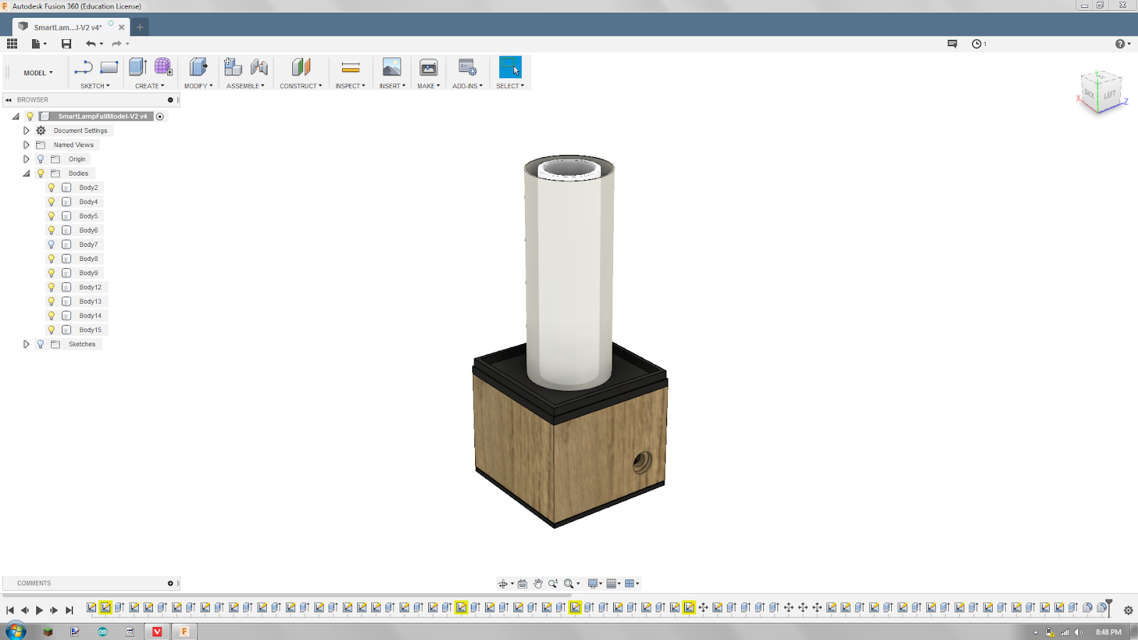
Below the cover and diffuser assembly, there's what I've called the "adapter plate". This interfaces with the shade and diffuser assembly on top, and the wooden part underneath.

The wooden part houses all the electronics (besides the LEDs and touch sensing pad), then below that is just a bottom cover, with a hole to access the USB port (for programming), and the SD card slot.

Now that I'd finished designing the physical aspect, software aspect, and electronics aspect, it was time to put it all together.
First, I needed to make the wooden part. That was an adventure in itself: I'm much more adept at electronics than I am with woodworking. I do like it though, and would like to get better...


Once the gluing was done, I sanded it, then drilled the hole for the power jack.


I should have drilled the speaker grill holes next, but I think I'd forgotten about them... So instead, I went ahead and applied a light finish with some boiled linseed oil. It brought out the natural color of the wood, without a heavy/glossy finish, and should work great for keeping the wood from getting dry and splintery.


Next, I did some modification so that the speaker would fit. The speaker I had was just a tiny bit wider (like 3MM) than the width of the space inside the wood- So to make it fit, I carved little grooves in the sides with a wood carving tool.


To drill the speaker grill holes in a (mostly) uniform pattern, I used a 3D printed template I designed to guide the drill bit. If I'd thought about it more, I'd have made it thicker so the bit would stay straight up/down. For a first attempt, I'd say it worked pretty well.


I should have drilled all the holes and done all the sanding before I finished it- Luckily, it was easy enough to re-apply some linseed oil over the speaker grill, once I was finished cleaning it up.
The only user input is a capacitive button on top. To make it, I glued some aluminum foil to a piece of cardstock, and cut it out in a nice round shape.


Then, I soldered a wire to it (aluminum foil is really hard to solder to), and glued the whole thing to the underside of the lampshade, on the top.


In a future version, I'd like to try some sort of mesh, as the foil blocks the light, and is visible from the outside of the lamp.

With all the pieces and parts made, tested, and working, it was time to put the lamp together for the last (haha) time.


I used a combination of hot glue and double-sided foam tape to hold everything in place, and taped all the connections with masking tape to keep them securely connected while I was assembling it. I also designed some 3D printed standoffs to mount the ESP and DC-DC converters to.

I then tested it, and it worked! I could not have been happier. A month of trial and error, and it finally worked!
I began using it, and it was great. My concerns about the RGB LED strip not being able to produce enough light was unfounded. It's not the equivalent of a light fixture, but it worked as well as the lamp I'd used before. The light was soft and not harsh on the eyes (perks of using RGB Leds- You get to set the color temperature), and the fading effect, activated with a quick tap to the top of the lamp, was visually pleasing.
After some use, I did notice it got somewhat hot inside, but I accounted it to the LEDs and just waste heat from some inefficiency in the DC-DC converters. It worked for about a month and a half, and then one day I came home and found it looping in the startup routine- Spiral pink lights up the lamp- Then reset. When you first power it on, it's supposed to show pink to indicate it's setting things up, then change to light blue to indicate everything was successful- But instead of changing, it just restarted. I tried non-intrusive methods of solving it- Unplugging it and plugging it back in, reprogramming it, etc. It seemed to work fine with USB plugged in, except the LEDs would flash glitchily and end up with each LED a slightly different hue than the others.
I decided it was a power issue (I thought that was over with!), and decided to take it apart. Here's what I found.

When I first started making this lamp, I didn't know much about wire guages and the amperage ratings for them. I've recently learned a bit about it (because I'm planning to build battery packs for an electric car), and realized that the tiny 22 guage wire I had connecting all the power was not enough for upward of 1.5A. The poor little wires had done their best, lasting for over a month before something broke. I'm still not exactly sure where the fault is, but I'm going to rewire it with properly sized wires (when I get the time), and see if that helps.
Once it is working, there are dozens of cool possibilities with the current hardware. The internet is like the ultimate sensor, and I can imagine all sorts of uses for an RGB IOT Lamp. Somewhere once I saw a "twitter world mood" lamp- Poll specific sites for key "mood" words, then based on what type of emotion is strongest, display a color associated with that. When you wake up, do you want to know if there's urgent news right away so you don't have to check your phone first thing? An IOT lamp could change colors/flash/whatever to let you know. There are lots of other possibilities, too.
Even as just a lamp, there's a lot of room for cool expansion. I was playing with a ported-down (arduino library) version of the NOAA Solar calculator to get it to "rise" with the sunrise- I didn't get it working, though the code is in the current program. You could have features like the lamp not letting you stay up too late reading, the lamp acting like a candle, and (one that I definitely plan on adding) the color temperature changing throughout the day- From a cool white/blue in the morning to energize you, to a orange-yellow glow in the evening, to help you relax in preparation for sleep.
There are hundreds of possibilities, which is why I'll be excited to get an instructable and YouTube video about it, thus officially releasing it as an open-source project to the public.
Of course, the design and files are open source. Right now I don't have anything posted anywhere, but if you'd like any resources, send me a message and I'll see what I can get you.
If you'd like to keep an eye on the project, go follow the github page! You can find it here: https://github.com/Bobcatmodder/IOT-RGB-SunriseAlarmLamp. Alternatively, if you like the things you see, consider checking out my YouTube Channel.

